File: Model Component anatomy.png
From Spire Trading Inc.
(Diagram of how Data, Styles, State, and Signals relate to the component. The component is represented as a rectangular boundary, each section is represented as a wire directed between or within the boundary.) |
(No difference)
|
Latest revision as of 09:02, 10 August 2023
Summary
Diagram of how Data, Styles, State, and Signals relate to the component. The component is represented as a rectangular boundary, each section is represented as a wire directed between or within the boundary.
File history
Click on a date/time to view the file as it appeared at that time.
| Date/Time | Thumbnail | Dimensions | User | Comment | |
|---|---|---|---|---|---|
| current | 09:02, 10 August 2023 | 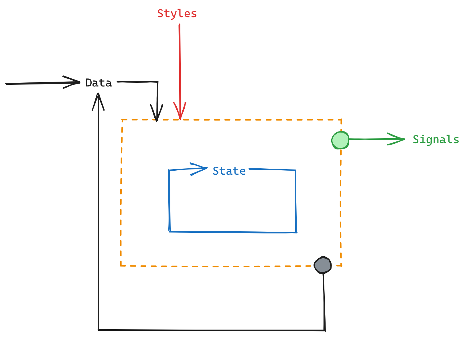 | 1,624 × 1,177 (112 KB) | Jon (talk | contribs) | Diagram of how Data, Styles, State, and Signals relate to the component. The component is represented as a rectangular boundary, each section is represented as a wire directed between or within the boundary. |
You cannot overwrite this file.
File usage
The following page uses this file: